Supplemental ideas that could work with the 2021 Winter Build Project!
If you haven’t heard of the Arduino, where have you been?! For those that are wondering, the Arduino is an open-source microcontroller platform that is inexpensive, easy to learn, and very well documented.
The Arduino microcontroller comes in many different packages, depending on the number of input/output pins you need, built in capabilities, speed, and memory requirements.
I’m lazy by nature, so for our 2021 Winter Build Project, there were two instances where the Arduino could come in handy to alleviate my need for work.
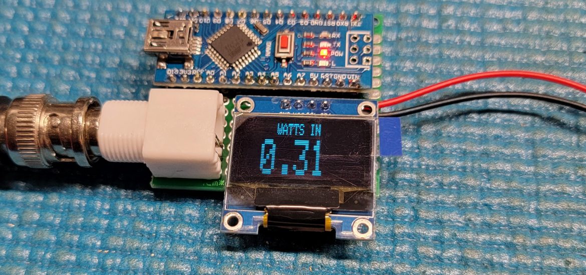
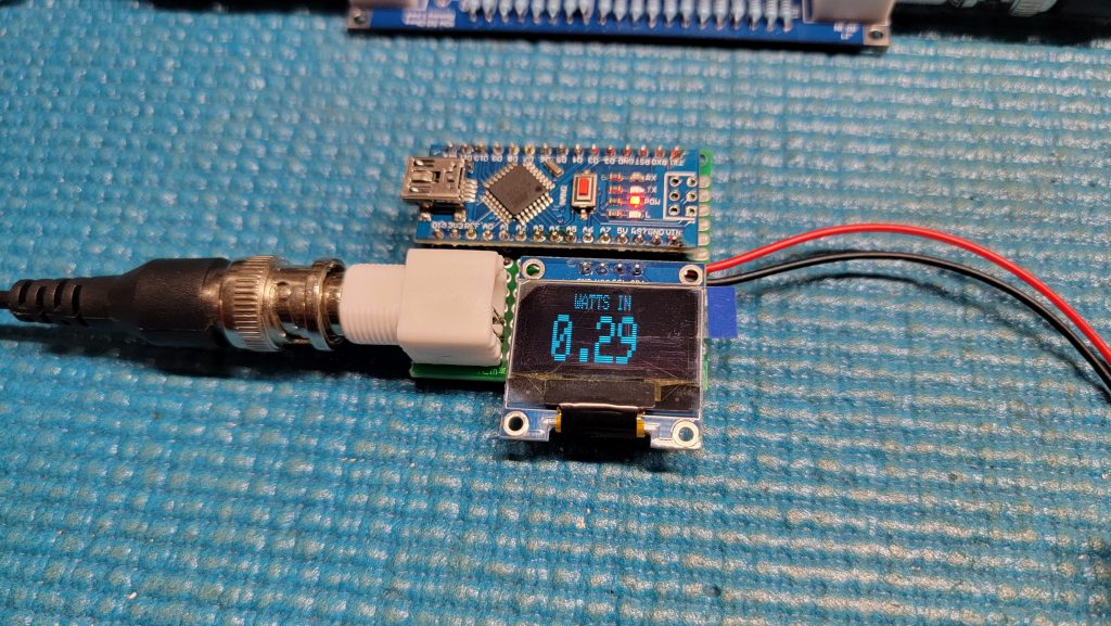
1 – To compute and display the wattage being transmitted into our dummy load
2 – To mash out the morse code needed to get the Pixie transmitting accurate CW (because my skills are terrible)
One thing to note, I had some bad experience in using 9v to power the Arduino Nano for the below projects, and instead powered the device from the USB port. I think it was due to using some very cheap Arduino Nanos.
Number 1 – Wattage
Parts:
- Arduino Nano
- 0.96″ I2C OLED Display Module
- 56k ohm resistor
- 2k ohm resistor
- Female BNC connector
- Power with 9v battery/holder or 5v USB power source
I found a great article in the November 2018 issue of QST to build a Dummy Load/Wattmeter on page 32.
The source code, and in-depth assembly manual is available here as a compressed ZIP file.
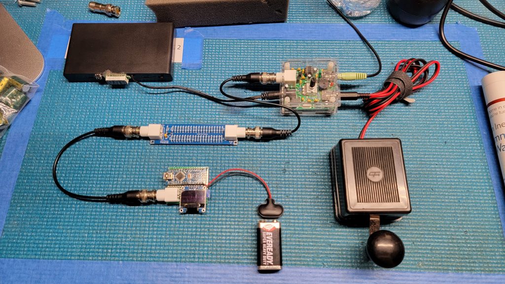
My modification was to not create the article dummy load (we just built one), and instead, modify the circuit to just include the dummy load we built, and connect via BNC cable.
The source code needs to be updated to include your actual measurements for the following variables:
#define MYDUMMYLOADOHMS         50.2    	  // This needs to be changed for yours. See article in QST

#define DIODEVOLTAGEDROP        0.370    	  // Voltage drop from diode
For the MYDUMMYLOADOHMS, just take a resistance measurement from J1 center pin to J1 outer ring on the Winter Build dummy load.
For DIODEVOLTAGEDROP, take a diode voltage measurement across D1 of the dummy load.

Number 2 – Beacon
Parts:
- Arduino Nano
- 100 ohm resistor
- 2n2222 transistor
- 10uF capacitor
- 1/8″ jack (to connect an aux cord between this and the Pixie
- 5v USB power source
This is a very simple project that allows you to modify the source code to include your message (“CQ CQ DE CALLSIGN/B”) near the bottom of the code. Once completed, just connect this to the Pixie, and have it transmit for you while you look yourself up on the ReverseBeaconNetwork!
void loop() {
  sendmsg("CQ CQ DE W4XXV/B") ; // example using my call sign
  delay(3000) ;
}
It is based on the project here (click).
Resources
Want to get started with the Arduino? Here are a few links to get you going.
- Getting Started – https://www.arduino.cc/en/Guide
- Lessons from Adafruit – https://learn.adafruit.com/category/learn-arduino
- Arduinos and Kits – https://www.amazon.com/s?k=arduino
- Books from ARRL – Microcontroller Projects for Amateur Radio and More Arduino for Ham Radio