Often we find ourselves with the need to share multiple antennas with a single transceiver, or multiple transceivers with a single antenna. So, is this actually possible?
The simple answer is yes, but we have to make sure that we understand the principles that are in use with the application to be able to do this safely. The NRVARC uses these devices to share a single multiband antenna with 3 stations during our field activations with great success.
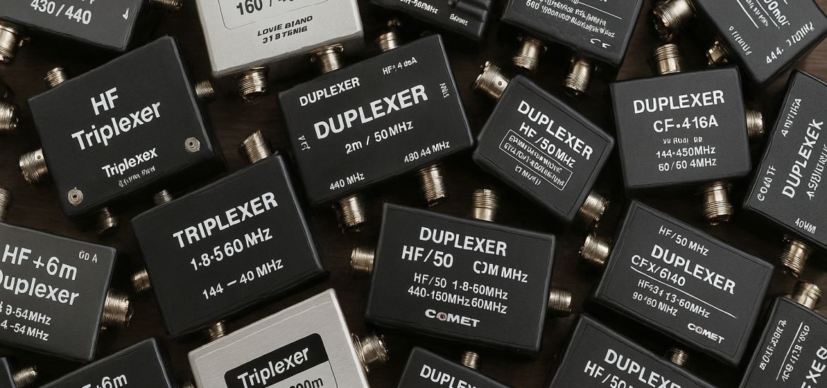
What is a multiplexer?
A multiplexer essentially is a traffic cop for frequency ranges. Depending on the application, this could mean that we split the one roadway into two or more lanes of traffic for a given frequency range. On one end of the multiplexer, the frequencies are all mixed in together. On the other end, each roadway (port) is designed to pass a specific frequency range. With either end, they are designed to work with a 50 ohm load, whether it be an antenna, transceiver, or dummy load. All lanes need to have a 50 ohm load connected. Don’t ask me, that’s just the way their designed.
What are some applications?
🔧 1. Feeding a Multiband Antenna to Multiple Radios
Use case: You have a single multiband antenna (e.g., a triband vertical or fan dipole) and want to connect multiple radios that operate on different bands.
How it works:
- A triplexer is used to split the antenna’s feedline into band-specific ports (e.g., HF, VHF, UHF).
- Each port is connected to a different transceiver operating on that band.
Example:
- A club station uses a Comet CF-4160 to run one 6m rig, and a UHF rig simultaneously on a multiband vertical.
🛰️ 2. Satellite Operation (Cross-Band Duplex)
Use case: Operating full-duplex satellites (like FM satellites) that require transmit on one band and receive on another at the same time.
How it works:
- A duplexer (diplexer) splits the feedline from a dual-band antenna (usually VHF/UHF) to separate the 2m TX and 70cm RX signals.
- This enables simultaneous TX/RX through the same feedline/antenna, and helps with desense issues for Mode-J satellites
Example:
- A Yaesu FT-991A used for satellites with a COMET CF-416C duplexer (more information here).
📡 3. Remote Stations / Shared Antennas
Use case: Multiple operators or radios sharing a remote station or antenna farm, where infrastructure is limited.
How it works:
- Multiplexers split a wideband antenna system into different band legs that are routed to different operating positions.
- Each operator gets access to a band-specific path, with proper filtering to avoid interference.
Example:
- Field Day site using a multiband DX Commander with a LowBandsSystems (10/15/20 meters) triplexer to allow three separate stations to operate on the same antenna simultaneously.
🏢 4. Single Feedline to Multiple Antennas
Use case: Limited feedline space (e.g., on a tower or through a wall), but multiple antennas at different bands.
How it works:
- Use a multiplexer at the shack end to split a single feedline into band-specific ports.
- Each port goes to a separate antenna via a diplexer or triplexer at the tower top.
Example:
- A vertical for HF and a Yagi for VHF/UHF sharing a single coax run using a duplexer on each end.
🔁 5. Transmit/Receive Isolation in Contesting or SO2R
Use case: In Single Operator Two Radios (SO2R) or multi-op contesting, radios on different bands operate simultaneously.
How it works:
- Multiplexers with high port isolation help keep RF from one radio out of the other radio’s front end.
- Often combined with band-pass filters for additional isolation.
Example:
- An SO2R station using a triplexer on a tribander to operate 10m and 20m simultaneously without inter-band interference.
⚙️ 6. Integrating Older or Specialized Gear
Use case: Using multiple single-band transceivers (or military surplus radios) on a modern antenna setup.
How it works:
- Use a triplexer to allow each radio to work only on its native band, while sharing one high-performance antenna.
Example:
- A setup with a 6m-only rig, a 2m FM mobile, and a 70cm packet TNC all using one vertical antenna via a triplexer.
📝 Summary of Benefits
| Benefit | How Multiplexers Help |
|---|---|
| Save coax runs | Use one feedline for multiple antennas or bands |
| Enable multiple radios | Share one antenna with proper band isolation |
| Support full-duplex | Key for satellite and repeater work |
| Reduce interference | With proper filtering, avoids RX overload |
| Compact installations | Ideal for portable and field use |
Won’t I damage another transceiver if sharing an antenna?
When we are sharing between multiple transceivers, it’s important to understand the isolation needed between ports. Energy from one transmitter can damage the receiver on another port if there isn’t enough isolation.
📡 Typical Isolation Targets for a Multiplexer
| Use Case | Recommended Isolation | Notes |
|---|---|---|
| Single radio, multiband antenna | >30 dB | Lower isolation is tolerable since only one transmitter is active at a time. |
| Multiple radios transmitting simultaneously (e.g., SO2R, Field Day, repeater systems) | >60 dB | High isolation is critical to prevent intermodulation, receiver front-end overload, and cross-band interference. |
| Duplex operation (simultaneous TX and RX on different bands) | >80 dB | For example, full-duplex cross-band repeat; poor isolation can desensitize or damage the RX. |
🔍 Why This Matters
If you’re transmitting on one port, insufficient isolation can:
- Leak signal into another port and overload or damage a receiver,
- Cause intermodulation distortion in adjacent radios,
- Create RF feedback or harmonics that reduce performance.
🧪 Real-World Examples
- Comet CF-4160 triplexer: ~60 dB isolation typical between ports (used for 1.8–30 MHz, 50 MHz, 144/430 MHz).
- Diamond MX-2000: ~60 dB isolation between ports; designed for up to 800W PEP, suitable for multiband HF/VHF/UHF.
- High-end contesting bandpass filters: Often >70–90 dB isolation between adjacent bands. (LowBandSystems and 4O3R)
Band-Pass Filters
Typical multiplexers for contesting often need help in achieving > 70 dB of isolation, so the addition of band-pass filters are recommended.
Band-pass filters are typically used after the multiplexer, on each band-specific leg (between multiplexer and transceiver), especially if:
- You’re running multiple transmitters simultaneously (e.g., in contesting or Field Day).
- You want to reduce harmonic emissions or inter-station interference.
They improve selectivity and isolation but also slightly reduce power due to insertion loss.
✅ Bottom Line Recommendations
| Situation | Minimum Isolation to Target |
|---|---|
| One radio, multiband antenna | 30 dB |
| Two radios, same antenna | 60 dB |
| Simultaneous transmit/receive | 80 dB+ |
If you’re designing or choosing a multiplexer, aim for the highest isolation you can afford or fit into your setup—especially if any simultaneous transmit/receive is involved.
Can you use a tuner with multiplexers?
You can, but you’re going to cause problems, and possibly damage things.
⚠️ Why This Causes Problems
Triplexers (and duplexers and filters) are frequency-selective RF splitters/combiners that assume:
- 50-ohm impedance on all ports,
- Specific frequency bands at each port (e.g., 20 meters, 40 meters, VHF, UHF),
- A matched system.
If you insert a tuner before the triplexer (between it and the transceiver), here’s what goes wrong:
❌ 1. Mismatch to the Triplexer
- The tuner attempts to match the transceiver to the load (in this case, the triplexer’s common port).
- But the triplexer’s internal filters are designed to see a consistent 50-ohm source and load.
- A mismatch from the tuner can detune the filters, leading to:
- Increased insertion loss,
- Reduced isolation between ports,
- Poor filtering performance,
- Risk of damaging the triplexer, especially at higher power levels.
❌ 2. Band Confusion
- Tuners work by presenting a different impedance at each frequency to the radio.
- Triplexers rely on clean band separation.
- The mismatch and potential spurious emissions from improper tuning can confuse the triplexer filters, possibly leaking RF into the wrong ports.
❌ 3. Wrong Role Assignment
- A triplexer is not a load—it’s a signal-routing device.
- The antenna is the real load.
- You should always maintain 50 ohms matching between the transmitter, filter, multiplexer, and load (antenna or dummy load). This means that you should attach a 50 ohm dummy load to any unused ports.
If you insert a tuner after the triplexer (between it and the antenna), the problem becomes that the tuner is going to impact all frequency ranges shared, not just one band, so you may have a match with one range, but throw everything off for another frequency range causing a terrible mismatch.
**Due to this, it is recommended to ONLY use multiband antennas that are resonant on the bands of interest in this configuration.
🔧 Summary
| Configuration | Result |
|---|---|
| Transceiver → Tuner → Filter → Multiplexer → Antenna | ❌ Bad: Filter sees mismatch, degraded performance |
| Transceiver → Filter → Tuner → Multiplexer → Antenna | ❌ Bad: Multiplexer sees mismatch, degraded performance |
| Transceiver → Filter → Multiplexer →Tuner → Antenna | ✅ Good: Filter sees 50 ohms, tuner handles mismatch, but you can only use one band |
| Transceiver → Filter → Multiplexer → Resonant Antenna | ✅ Perfect: Tuner not needed |
Links to Products
Here are some links to products that perform the actions as given above. These are not endorsements of the products but rather information for you to start your investigation to find what will meet your specific needs.